|
Distributed Sensing of Morphing Structures
(Sponsor: ARO, NSF, Airbus)
Monitoring the shape and health of morphing structures is essential for their effective and safe operation. However, current sensing systems such as fiber optic sensors are expensive, rigid, and unsuitable for monitoring large shape changes without being susceptible to failure or performance degradation. Therefore, it is the purpose of this study to present a novel class of sensors that does not suffer from these serious limitations and can be used to simultaneously measure the shape and the health of a wide variety of morphing structures.
The proposed sensor system relies in its operation on a specially configured distributed network of wires that are embedded in the composite fabric of these structures. The output of the sensor network is wirelessly transmitted to a control processor to compute the linear and angular deflections, the shape, and maps of the strain distribution and power flow over the entire surface of the morphing structure. The deflection and shape information are vital to ascertain that the structure is properly deployed and that its surfaces are operating wrinkle-free. The strain map ensures that the structure is not loaded excessively to adversely affect its service life. While the power flow map provides a metric that uniquely identifies the structural health in a manner that mimics biological systems which tend to redistribute the load and redirect its path away from the injured sites. Such a novel biomemetic metric is capable of identifying both the location and extent of VERY SMALL damages.
The main approach adopted in this study to implement the objectives of the project is as follows:
This objective aims at the development of the theoretical basis for the design of sensor networks for morphing structures. The proposed development will be based on the non-linear theory of finite elements to extract the transverse linear and angular deflections as well as the in-plane longitudinal deflections. Emphasis will also be placed on developing the equations necessary to compute the power flow in morphing structures in terms of the transverse deflection and in-plane deflections and their derivatives using the concepts of non-linear mechanics.
The theoretical equations governing the operation of the sensor network will then be utilized to optimize the parameters of the sensor network in order to select the length of the different sensor segments such that the equations of the different degrees of freedom are decoupled. More importantly, the optimization strategies will be employed to select the number and spatial spacing of the different sensor segments in order to avoid spatial aliasing and to ensure achieving the desired accuracy of predicting the shape, the wrinkling, and defects.
Prototypes of the sensors will be built, integrated in two types of morphing structures, and then tested under various static and dynamic loading conditions to determine the time and frequency response characteristics of the proposed sensor network as compared to other conventional sensor systems. The two morphing structures to be considered are structures with variable cambered span (as the hyper elliptic cambered span HECS wing of NASA) and structures with variable camber (as the wing of the Advanced Fighter Technology Integration aircraft AFTI/F-111). Other tests will be conducted to evaluate the ability of the proposed sensor network configurations to predict the extent and location of known defects placed on the wing at specific locations. The tests will aim at determining the accuracy of identifying the defects and the threshold of effectiveness of the proposed sensor in locating these defects.
iv. Transfer the developed technology to our industrial partner: Airbus
In this task, the developed distributed sensor network will be integrated in the morphing wings of our industrial partner: Airbus.
The proposed distributed sensor for monitoring the LARGE deformation of morphing structures using networks of distributed wire sensors to monitor the shape of a morphing beam. For large deflections, the proposed sensor network will be based on the non-linear theory of finite elements to extract the transverse linear and angular deflections as well as the in-plane longitudinal deflections.
The concept of the proposed distributed network sensor can best be understood by considering the one-dimensional flexible beam-like structure shown in the figure below. For morphing structures, the deflections will be determined using two and three-dimensional sensor networks.
The strain ε(x) in a wire embedded inside the beam at a distance 'a', from its neutral axis, can be determined from the following von Karman strain-displacement relationships:
| |
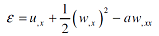 |
(1) |
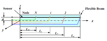
Flexible beam with distributed sensor
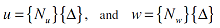
In the figure, the wire sensor is divided into N segments in order to extract N unknown degrees of freedom, i.e. nodal deflections, as will be explained later. The axial and transverse displacements, u and w, can be approximated as follows:
| |
 |
(2) |
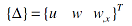
where {Nu} and {Nw} are the classical shape functions for axial and transverse displacements, and {Δ} is the nodal deflection vector defined as:
| |
 |
(3) |
Substituting equations (2) and (3) into equation (1) yields:
| |
 |
(4) |
The change ΔLs in the length of a wire segment s can be determined from:
| |
 |
(5) |
Substituting equation (4) into equation (5) results in:
| |
 |
(6) |
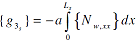
where:
| |
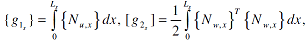 |
(7) |
| |
 |
In equation (6), the nodal vector {Δ} has N degrees of freedom (DOF). For example, if the beam is mounted as a cantilever beam and is represented by one finite element, then the beam has 3 DOF, i.e. {Δ}={u1 w1 wx1}'. These degrees of freedom are those of node 1. Hence, the wire sensor must be divided into at least, three segments such that N=3. Then, equation (6) can be put into a matrix form by considering the changes of length of all the N wire segments to give:
| |
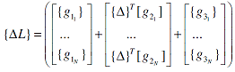 |
(8) |
| |
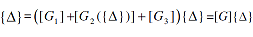 |
where {ΔL}={ΔL1 ΔL2 ..... ΔLN}'. Note that the matrix equation (8) represents a set of N equations in the N unknown degrees of freedom of the vector {Δ}. The elements of the vector {Δ} can be computed by inverting the matrix [G]. However, such a computational process is iterative in nature as matrix [G2] is a function of the unknown deflection vector {Δ}. The iterative solution of equation (8) is given by:
| |
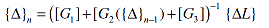 |
(9) |
where n is the nth iteration, and {Δ} at n=0 is the initial guess for the deflection vector given by:
| |
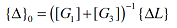 |
(10) |
It is important here to note that the proposed distributed wire sensor is in effect a distributed strain gage sensor. Such a distributed nature of the sensor has many inherent advantages. First, it makes the placement of the sensor and the tapping points insensitive to the location of the nodes of vibration. This of course is not the case for conventional discrete strain gages where the sensors cannot be placed at these nodes. Second, because the distributed wire sensor relies on integrating the strain along the wire segments, as described by equation (5), its output signal will be less noisy than that of conventional strain gages and high signal-to-noise ratios can be obtained. Third, the sensor because of its embedded nature, can also detect structural failures by monitoring the failure of any wire segment. These advantages make the distributed wire sensor suitable for accurately monitoring the deflection, shape, vibration, and integrity of morphing structures.
Most importantly, the proposed distributed wire sensor has unique characteristics which stem from its interpolating capabilities as can be ascertained from equations (2) and (4). Hence, once the nodal deflection vector {Δ} is computed, the deflections u and w at any location x can be easily determined using the interpolating functions {Nu} and {Nw} as given by equation (2). Also, the angular deflection θ(x), at any location x, can be computed from:
| |
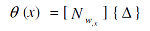 |
(11) |
Similarly, the strain field 'ε' can then be determined using equation (4). Such interpolation capabilities of the distributed wire sensor render it suitable for monitoring the entire deflection and strain fields for large structures with only a small number of wire segments.
The manufactured morphing beam/sensor system is clamped in a cantilever arrangement as shown in the figure below and accordingly, the shape of the beam can be determined completely using the three-section sensor. These three sections enable the computation of the three degrees of freedom (u, w, wx) at the free end of the beam which are then used to generate the complete deflection and strain maps over the entire surface of the beam.
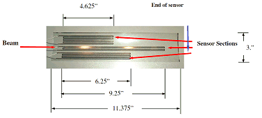
Distributed sensor assembly
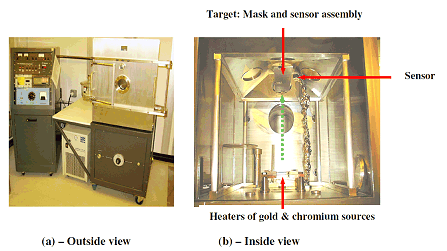
METRA box coater
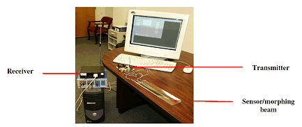
Photograph of morphing beam/sensor, transmitter and receiver system
The figures below show qualitative and quantitative comparisons between the actual and measured shapes of the morphing beam for two different morphing configurations. It is evident that the simple configuration of the three-section sensor is capable of monitoring very complex shapes of the morphing beam.
The user inputs a desired shape of the morphing structure, the computer drives the motors to generate that shape, and the sensor monitors the shape as structure morphs from an initial shape to the desired shape.
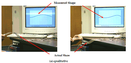
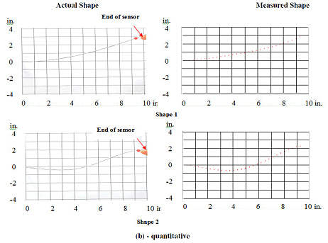
Comparison between actual and measured shapes of a morphing beam
W. Akl, S. Poh and A. Baz, “ Wireless and Distributed Sensing of the Shape of Morphing Structures”, Journal of Sensors and Actuators A: Physical, Vol.14, pp. 94-102, 2007
A remotely-controlled model aircraft with morphing wings is built and its performance is evaluated. The aircraft relies in its operation on a network of distributed sensors that are embedded in the composite fabric of the wings to monitor the wing shape during morphing. The output of the sensor network is wirelessly transmitted to the ground command computer to simultaneously map the wing shape and the strain distribution of the aircraft during flight. The error between the actual wing shape and the desired shape corresponding to a specific aircraft mission is determined. The necessary control action is computed according to a selected control law and the resulting action is tele-metered from the ground computer to the modified servo-motors of the flying aircraft to compensate for the shape errors.
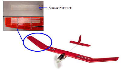
Model morphing aircraft
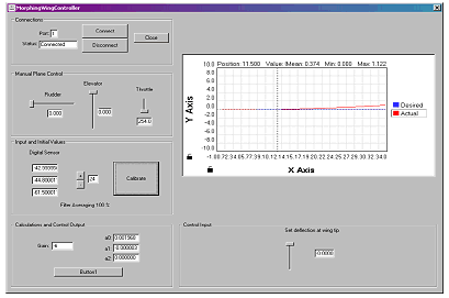
Graphical User Input for Control of Morphing Aircraft
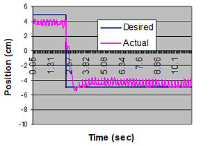
Performance of the morphing wing controller
J. Smoker and A. Baz, “Remote Control of a Morphing Model Aircraft with Distributed Sensors”, Sensors and Smart Structures Technologies for Civil, Mechanical, and Aerospace Systems, edited by M.Tomizuka, C.-B. Yun, V. Giurgiutiu, Proc. of SPIE Volume 6529, paper # 6529-23, 2007.
A distributed wire sensor network is embedded inside car seats to enable the measurements of the weight of the occupants, location of their center of gravity, and spatial orientation of their bodies. Based on these measurements, intelligent decisions can be made to ensure their comfort and safety particularly in case of accidents. Appropriate activation of the inflatable bags according to the weight and position of the occupants will be critical to avoiding unnecessary and undesirable injuries.
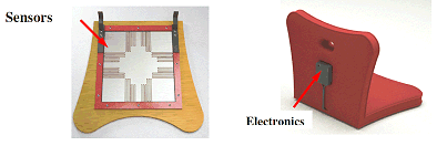
Structure of the car seat
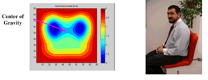
Output of car seat sensor
A. Baz and J. Smoker, “Distributed Sensor for Smart Car Seats”, 2008 NSF Engineering Research and Innovation Conference, January 7-10, 2008, Knoxville, TN.
The basic concepts behind the use of the proposed sensor as an effective means for health monitoring are deep rooted in the natural approaches adopted by biological systems to reveal the presence of injuries or defects. For example, biological systems tend to redistribute the load and redirect its path away from the injured or defective sites.
The deflection profiles of a beam-like morphing structure can be used to extract the structural power flow as an effective criterion for identifying the exact location of the defects. For example, knowing the distribution of the axial deflections 'u' and transverse deflections 'w' of a beam, the power 'P' can be determined from:
| |
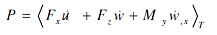 |
(1) |
where <> and the subscript 'T' denotes the time average, and the cross section of the beam is in the xz rectangular coordinate plane. In equation (1), Fx is the axial force, u-dot is the axial velocity, Fz is the transverse shear force, w-dot is the transverse velocity, My is the bending moment, and wx-dot is the rotational velocity about the beam axis y. Hence, the first term in the above expression represents the power in the longitudinal wave and the second and third terms added together define the power in the bending wave. Note also that Fx, Fz, and My can be determined from the spatial derivatives of the deflections u and w as follows:
| |
 |
(2) |
with EA and EI denoting the longitudinal and flexural rigidity.
Hence, the spatial distribution of the power flow can be determined by combining equations (1) and (2) as follows:
| |
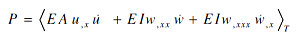 |
(3) |
i.e., the power can be determined in terms of the spatial and temporal derivatives of the deflections u and w.
A one meter long beam with flexural rigidity EI=1Nm2 is used to validate the developed concepts. The beam is mounted in a cantilevered configuration and is provided with two-segment wire sensor as shown below.
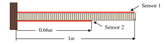
The numerical beam with two-segment wire sensor
The beam is divided into 60 elements and a small mass of 0.01 of the mass of the beam element is bonded to the beam at different locations to simulate a defect. This simulated defect has a very small mass which is about 0.016% of the beam mass. The beam is transversely excited at its free end by a sinusoidal force that has a frequency equals to the beam first natural frequency.
The Figure below demonstrates the effectiveness of the power flow criterion in identifying the location of the defect using a MATLAB Graphical User Interface (GUI) which is developed using the approach outlined above.
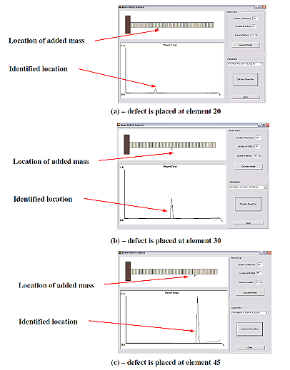
Identification of locations of small defects
A. Baz, “Structural Health Monitoring using Power Flow Metric”, Sensors and Smart Structures Technologies for Civil, Mechanical, and Aerospace Systems, Smart Structures/NDE Conference 2009, edited by M.Tomizuka, C.-B. Yun, V. Giurgiutiu, Proc. of SPIE Paper # 7292-81, 8 - 12 March 2009, San Diego, California, USA.
To see the videos, double-click on the image.
QuickTime Format. Quicktime Player required for viewing.
You can download a free player HERE.
Distributed Sensing of Shape of Morphing Structure |
| |
|
|
Distributed Sensing of Shape of Inflatable Structure |
Top of Page
|